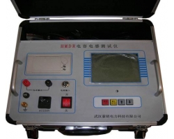
Single-Phase Capacitance and Inductance Tester
I. Product Overview
The single-phase capacitance and inductance tester is an important device for achieving reactive power balance in the power system. In recent years, reactive power issues have received widespread attention from power departments, and complete sets of reactive power compensation devices have been widely deployed in distribution networks. Power supply requires real-time balance of active and reactive power in the system. Therefore, reactive power compensation devices should meet the requirements of automatic tracking and real-time compensation, which inevitably leads to frequent switching of reactive power compensation capacitor banks. The switching operations of capacitor banks can generate overcurrent and overvoltage surges, causing damage to capacitors.To ensure equipment reliability,early detection of capacitor defects to avoid fault expansion,regular testing is required.On-site, capacitors are typically connected in parallel groups,and the traditional method is to disconnect the capacitor busbars and then use an old-style capacitance meter for measurement. Since a capacitor bank consists of dozens to hundreds of small capacitors,the workload of disconnecting wires to measure capacitance is heavy, and frequent disconnection can cause screws to strip or not be tightened, leaving safety hazards,and it can also easily cause secondary damage to capacitors.Therefore, there is a strong need for a testing instrument that can measure the capacitance of each small capacitor without disconnecting wires, reducing the burden on maintenance personnel, improving maintenance efficiency, and enhancing the safety of distribution network operation.
In response to the actual on-site situation, our company has conducted research and ultimately developed an instrument that uses a new test method for measurement, namely the "Capacitance and Inductance Tester". This instrument can measure individual capacitors in a parallel capacitor bank without disconnecting wires, and it can also measure the inductance of various reactors. Additionally, it can measure current under power frequency conditions. The instrument features convenient wiring and simple operation, reducing the workload of maintenance personnel, greatly improving on-site testing efficiency, and providing safety assurance for the normal operation of the power grid.
II. Functional Features
This instrument can measure the capacitance of individual capacitors in a parallel capacitor bank without disconnecting wires (both single-phase and three-phase capacitors can be measured). It can also measure the inductance of various reactors and can be used as a power frequency current tester. It serves three purposes in one, meeting various on-site needs.
During measurement, the instrument displays the measured capacitance or inductance value, and can also display voltage, current, power, frequency, impedance, phase angle, and other data for better analysis of the test sample's condition.
The instrument uses a 240×128 large-screen backlit LCD display, which is clearly visible both day and night, with Chinese menu prompts for easy operation.
The instrument is equipped with a large-capacity non-volatile memory: it can store 50 sets of measurement data.
The instrument has a built-in high-precision real-time clock function: it can calibrate the date and time.
The instrument comes with a high-speed micro thermal printer: it can print measurement and historical data.
The instrument has overcurrent protection for the test power supply: a short circuit in the power output will not damage the instrument.
III. Technical Specifications
Output Voltage: ~2V, ~20V
Output Current: ≤20A
Measurement Range: Capacitance: 0.1uF~4000uF
Inductance: 0.1mH~20H
Current: 1mA~20A
Voltage: 0~25V
Capacity: 0~20.000kvar
Measurement Accuracy: Capacitance: ±(1%+2 digits)
Inductance: ±(1%+5 digits)
Current: ±(1%+2 digits)
Voltage: ±(1%+2 digits)
Capacity: ±(1%+3 digits)
Working Conditions: Temperature: -10℃~+40℃; Relative Humidity: ≤85%
Power Supply: AC 220V±10%, 50Hz
Dimensions: 400mm×320mm×180mm
Weight: 5kg
IV. Product Configuration
1. Host: 1 unit
2. Test leads: 1 set
3. Power cord: 1 piece
4. Thermal printer paper: 2 rolls
5. Fuse: 2 pieces
6. Instruction manual: 1 copy
7. Certificate of conformity: 1 copy
8. Warranty card: 1 copy