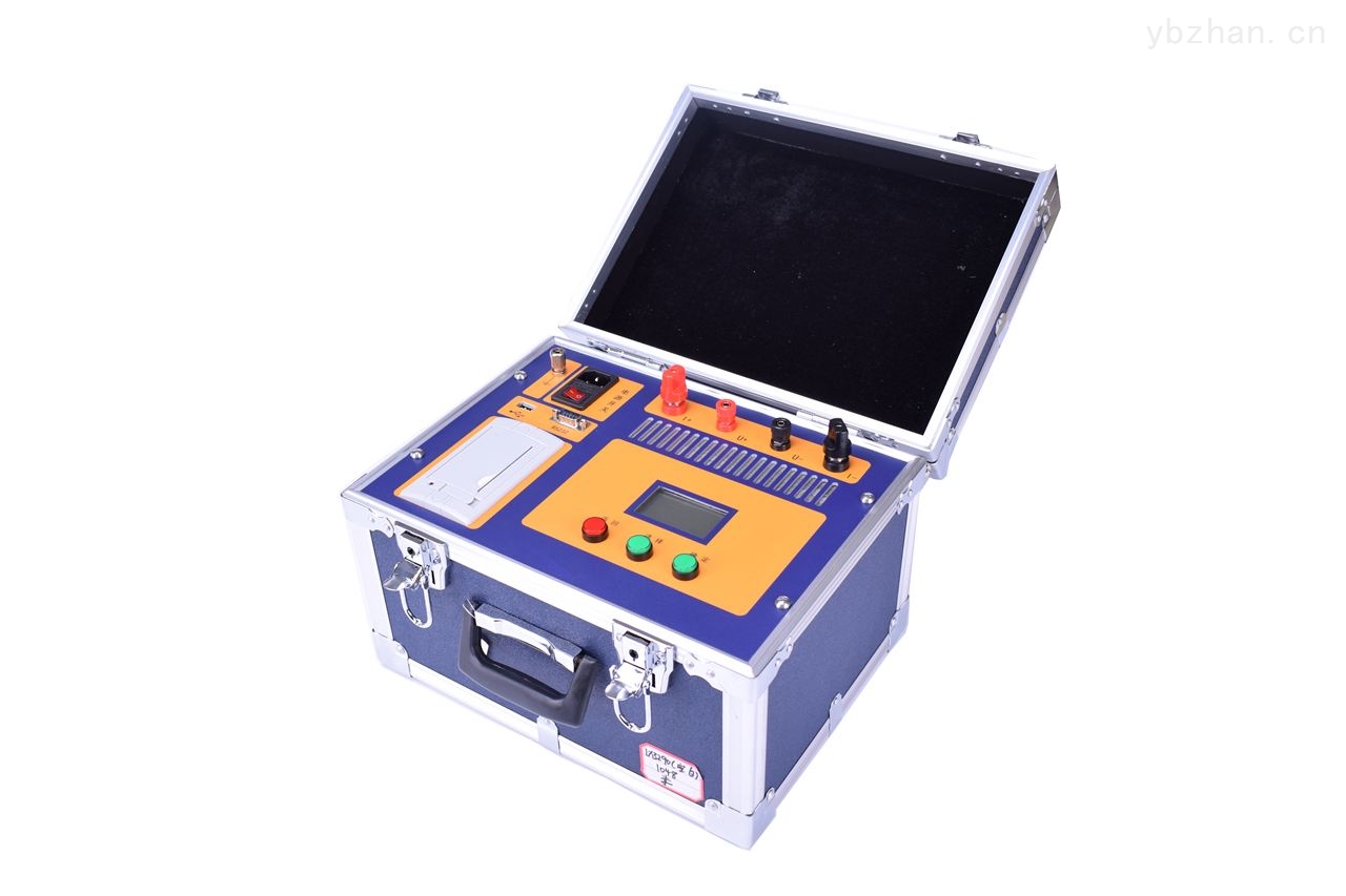
Contact Loop Resistance Tester
Currently, the conventional QJ44 double-arm DC bridge is commonly used in power systems for contact resistance measurement. However, the test current of such bridges is only at the mA level, making it difficult to detect defects such as reduced cross-sectional area of loop conductors. When measuring the contact resistance of high-voltage switch conductive loops, the measured value may be several times larger due to the influence of oil film and oxide layer between contacts, failing to accurately reflect the true contact resistance. To address this, the Ministry of Electric Power standard SD301—88 "AC 500KV Power Equipment Handover and Preventive Test Procedures" and the new edition of "Preventive Test Procedures for Power Equipment" stipulate that the measurement current for contact resistance of circuit breakers and disconnectors should not be less than DC 100A, to ensure accurate test results.Ensure accurate test results.
It is designed based on the People's Republic of China electric power execution standard DL/T845.4-2004, combining high-frequency switching power supply technology and digital circuit technology. It is suitable for measuring the loop resistance of switch control equipment. The test current adopts the national standard recommended DC 100A. The loop resistance can be directly measured under a current of 100A and displayed digitally. This loop resistance tester features accurate measurement and stable performance, meeting the requirements of on-site high-voltage switch maintenance in power and power supply departments and loop resistance testing in high-voltage switch factories.
1. Technical Indicators
Measurement Range: 0-1999μΩ
Resolution: 1μΩ
Measurement Current: >100A/200A DC
Measurement Accuracy: 0.5 class
Display Mode: LCD display, result printing
Operating Temperature: -10℃~50℃
Operating Current: AC220V±10%
Dimensions: 290×280×240
Weight: 6.2Kg
Contact Loop Resistance Tester
2. Working Principle
This device is equipped with a built-in 100A/200A switching power supply, enabling constant current 100A/200A dual-loop real-time tracking testing. This ensures accurate test results.
3. Operating Procedure
1. Connect the wires according to the four-terminal method.
2. Turn on the power.
3. Press the Measure/Print key (if the displayed current A value is less than 100A/200A, it can be corrected via the panel current fine-tuning).
4. After the measurement value is displayed, if data needs to be saved, press the Measure/Print key for three seconds to print the data.
5. After measurement, please turn off the power.
6. Please take care of the test clamps.