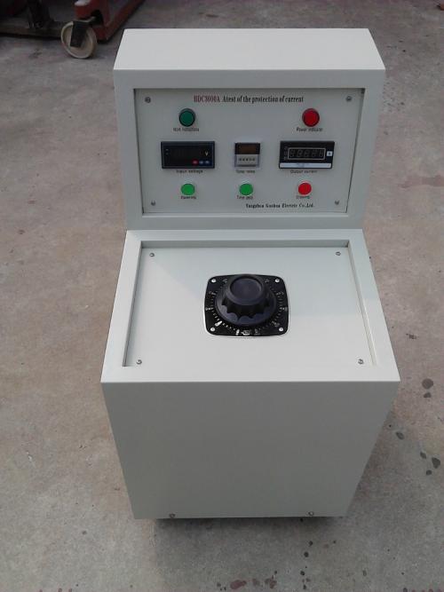
2000A High Current Generator
Product Introduction
The 2000A High Current Generator adopts a split or integrated structure according to the output current size. The product is relatively small in size and light in weight. It also features stepless adjustment of output current, balanced current rise, wide load variation range, reliable operation, simple operation, and safety. It is an ideal device for current rise or temperature rise tests.
The 2000A High Current Generator is specially designed and manufactured for power departments and industrial/mining enterprises to conduct current load tests and temperature rise tests on various switches, current transformers, and other electrical equipment during electrical equipment testing.
Technical Parameters
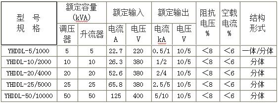
Working Power Supply: 220V or 380V ±10% 50HZ
Output Current: 0~10000A (selectable by user)
Output Voltage: 5V or 10V (selectable by user)
Ambient Temperature: -10℃~40℃
High Current Generator Panel and Functions
1. High Current Output Terminal
2. Power Indicator Light
3. Power Input Terminal: AC: 220V power is input here.
4. Ground Terminal. For safety, this terminal should be grounded.
5. 4 1/2 LCD Digital Current Meter.
6. Current Output Button. Press this button to output high current; the output indicator light turns on.
7. Current Cut-off Button. Press this button to cut off high current; the output indicator light turns off.
8. High Current Adjustment Knob.
9. Ammeter Calibration Adjustment Hole. Used when metrological verification of the meter is required. During verification, lift the circular seal of the hole and adjust with a small flat-head screwdriver or watchmaker's screwdriver. After adjustment, restore the circular seal.
Working Principle
The circuit is shown in the diagram. AC: 220V power is input from X, -X, adjusted by the TY voltage regulator, controlled by K1, and the T current booster increases the current, outputting high current through the ammeter A from Xl~X. When the two sets of coils are connected in parallel, it can output 1000A current with a maximum no-load voltage of 5V; when the two sets of coils are connected in series, it can output 500A current with a maximum no-load voltage of 10V.
Precautions
1. The cross-section of the input power cable of this tester should be greater than 2mm², and the cross-section of the high current output connecting cable should be greater than 100mm², and the length of the output connecting cable should be shortened as much as possible.
2. As long as the output current requirement can be met, use parallel output as much as possible.
3. Avoid continuous output for a long time.
4. For safety, the grounding terminal should be reliably grounded.
Usage Method
1. Connect the working circuit according to the electrical schematic diagram. The transformer casing, operation console, etc. must be properly grounded.
2. Turn on the power supply. The green indicator light on the operation console turns on. Press the start button, the red indicator light turns on, and the current booster waits to boost the current.
3. Rotate the voltage regulator evenly clockwise, and pay attention to the output current indication on the operation console until the required high current is reached. To ensure test accuracy, a standard ammeter can be connected in series at the meter terminal.
4. During the test, if any abnormal phenomenon is found, immediately cut off the power supply, find out the cause, and then conduct the test again.
5. After the test, the voltage regulator must be returned to zero, press the stop button to cut off the power supply, and then cut off the working power supply before removing the test wiring to ensure safety.