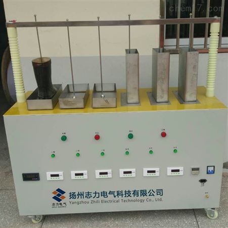
Auxiliary Insulation Tool Testing Device
1. Auxiliary Insulation Tool Testing Device Introduction:
The Insulating Boots (Gloves) Withstand Voltage Tester is independently developed and produced based on the test regulations for insulating boots (gloves) and following the opinions of the majority of users. This product adopts automatic voltage rise (fall), automatically reads the leakage current of each test object, and the entire process is fully automated, automatically printing test data, effectively solving the previous irregular testing methods, thereby simplifying test procedures and improving test speed. It is reliable, durable, fast in testing, and improves work efficiency.
6. High voltage and high voltage leakage current can be read directly, and unqualified test products can be automatically identified, with a high degree of intelligence.
7. Equipped with overcurrent and overvoltage protection. The protection is accurate and rapid, effectively ensuring the safety of personnel and equipment.
8. Precise voltage control capability with small voltage control error;
9. Time setting range: 1 second to 9999 seconds;
10. Can test 3 pairs of insulating boots (gloves) simultaneously, and read the leakage current of each one, accurately judging unqualified insulating boots (gloves).
3. Auxiliary Insulation Tool Testing Device Price Technical Parameters:
1. Supply Voltage
◇Voltage: AC 220V, allowable deviation: -20%~+15%;
◇Frequency: 50Hz, allowable deviation -4%~2%;
2. Output Voltage: 0-50kV
3. Capacity: 5kVA
4. Number of Test Objects: 6 per time, customizable to 8, 10, 12
5. Measurement Data: Can display and print the voltage value and leakage current value of each test object
6. Overcurrent Protection: Overvoltage protection; custom time, voltage, and leakage current values
7. Display Method: Dot matrix LCD display, full Chinese menu operation, with printing
8. Measurement Accuracy
◇Voltage ±1.0% (±3 digits)
◇Current ±1.5% (±3 digits)
4. Test Steps:
1. Add two-thirds of water to the water tank and fix it on the insulating platform.
2. Place the insulating boots and insulating gloves filled with water into the water tank. The insulating gloves are clamped with the insulating clips on the probe. The upper openings of the insulating boots and gloves must not be wetted, keeping the upper openings dry.
3. Adjust the tightening screws on the high-voltage tube, insert the probe into the water inside the insulating boots and gloves, and tighten the screws to fix the probe. 4. Ground the water tank box to the grounding post, connect the socket of the water tank box to the output socket of the control box, and turn the milliammeter switch on each water tank box to the "Off" position.
5. Connect the power socket of the control box to a 220V power supply and ground the grounding terminal.
6. Set the test time and overcurrent protection value.
7. Before turning on the power, return the voltage regulator to zero, close the knife switch, and the disconnect button light will be on. If an alarm is needed, press the alarm switch, and the alarm will sound and light. Press the start button, the start button light will be on, and the alarm will stop, indicating that power is on and waiting for voltage increase.
8. Rotate the voltage regulator handle clockwise at a uniform speed to increase voltage, and closely monitor the control box instruments and the milliammeters on the water tank box.
9. If the milliammeter on the water tank box is abnormal, turn the corresponding milliammeter switch to the "On" position to protect the milliammeter from overcurrent damage.
10. When the required voltage is reached, turn on the time relay switch, and the time relay starts timing.
11. When the time relay reaches the set time, the alarm will sound again, reminding that the withstand voltage time has expired.
12. Rotate the voltage regulator handle counterclockwise to reduce voltage, then turn off the time relay switch and press the disconnect button, pull down the knife switch, and the test ends. 13. Unless the test allows, never suddenly cut off power.
14. If the test object short-circuits or breaks down during the test, the overcurrent setting device will act to cut off the high-voltage output.