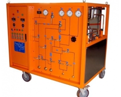
Analog partial discharge testers are one of the indispensable tools in the maintenance and fault diagnosis of power equipment. Despite the increasing popularity of digital technology, analog partial discharge testers still hold a place in the power industry due to their reliability and stability. This article aims to introduce the basic principles, construction, usage methods, and precautions of analog partial discharge testers.
Working Principle
Analog partial discharge testers mainly rely on analog electronic technology to detect partial discharge phenomena in power equipment caused by insulation material defects or other reasons. When partial discharge occurs in the insulation medium of high-voltage power equipment, it is accompanied by a series of physical phenomena such as electromagnetic radiation, acoustic waves, light, and the generation of chemical substances. Analog partial discharge testers can capture these phenomena and analyze and diagnose the partial discharge situation through built-in sensors and signal processing systems.
Specifically, the working process of an analog partial discharge tester is as follows:
Generation of pulse current: Under the test voltage, pulse current is generated near the partial discharge point.
Signal acquisition: The pulse current signal is transmitted to the input unit of the tester through coupling capacitors or other sensors.
Signal amplification: The low-noise preamplifier in the input unit amplifies the signal.
Signal selection: The filter amplifier selects signals within a specific frequency range.
Signal amplification and processing: The main amplifier further amplifies the signal, and zero-marking pulses may be added to assist subsequent processing.
Display: Discharge pulses are displayed on the oscilloscope screen, and the peak value can be displayed through the pulse peak meter.
Construction
The main components of an analog partial discharge tester include:
Coupling capacitor: Used to capture the pulse current generated by partial discharge.
Input unit: Includes preamplifier and signal processing circuits.
Filter amplifier: Used to select signals within a specific frequency range.
Main amplifier: Further amplifies the signal.
Oscilloscope: Used to display the waveform of discharge pulses.
Pulse peak meter: Used to display the maximum amplitude of the pulse.
Control and display interface: Includes display screen and operation buttons, used to display detection results and control the detection process.
Power module: Includes battery and charging interface, used for power supply.
Usage Methods
Startup preparation: Check battery level and ensure sensors are connected correctly.
Select detection mode: Choose the appropriate detection mode based on the object being tested.
Connect sensors: Place the coupling capacitor or sensor in an appropriate position on the equipment under test.
Data acquisition: Start the instrument to begin collecting data.
Data analysis: Observe signal strength, waveform, and other characteristics on the display screen.
Result recording: Record abnormal readings and their locations.
Follow-up measures: If abnormalities are detected, further diagnostic or repair measures are needed.
Precautions
Safe operation: Ensure all safety regulations are followed before conducting tests.
Environmental factors: Conduct tests in a quiet environment as much as possible to reduce the impact of background noise.
Equipment check: Before use, check battery level, date, time, and functionality.
Signal check: Ensure a slight, uniform electrical noise is heard in the earphones, and the curve drawing area on the test interface shows the center line aligned with 0dB, with the average value 10dB lower.
Save results: After confirmation, click the save button on the device screen to store the test results for later management and analysis.
Application Fields
Analog partial discharge testers are widely used in multiple fields:
Power systems: Used for condition monitoring of power equipment such as transformers, cables, and switchgear.
Manufacturing: Used for quality control of electrical equipment such as motors and generators.
Research institutions: Used for research and development of new materials and technologies.
Aerospace: Used for condition monitoring of aircraft electrical systems.
Conclusion
Although analog partial discharge testers are not as advanced as digital technology, their stability and reliability make them important tools in power system maintenance. They help technicians quickly identify potential fault risks inside electrical equipment, solve problems early, and ensure the healthy operation of electrical equipment. With the development of technology, such instruments will continue to play an important role and, in some cases, supplement or replace more advanced digital technology.