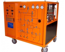
A transformer partial discharge tester is a specialized device used to detect partial discharge phenomena inside transformers in power systems. By capturing electromagnetic wave signals generated by partial discharges, this instrument helps maintenance personnel identify potential fault points in a timely manner and prevent sudden accidents in the power system. This article will provide a detailed introduction to the working principle, technical characteristics, and application scope of the transformer partial discharge tester.
Working Principle
The working principle of the transformer partial discharge tester is based on the electromagnetic wave signals generated by partial discharges. When partial discharge occurs inside a transformer, a series of physical phenomena are produced both inside the equipment and in the surrounding space, including electromagnetic waves, ultrasonic waves, etc. The transformer partial discharge tester captures these electromagnetic wave signals, processes and analyzes them, helping technicians locate and assess the degree of partial discharge.
Technical Characteristics
The main technical characteristics of the transformer partial discharge tester include
Non-invasive detection: Testing can be performed without disassembling or interrupting equipment operation.
Accurate positioning: It can accurately determine the location of partial discharge.
Easy operation: Testing can be conducted with simple connections and settings.
Immunity to power signal interference: It can operate independently of the power system's operational status.
High sensitivity: It can capture weak electromagnetic wave signals.
Multi-mode detection: It is typically equipped with various sensors, such as ultrasonic sensors, ground wave sensors, ultra-high frequency sensors, etc., enabling detection in multiple modes.
Application Scope
The transformer partial discharge tester is widely used in various fields of power systems, including but not limited to:
Voltage transformers: Detecting partial discharge inside voltage transformers.
Current transformers: Assessing the internal insulation condition of current transformers.
Power transformers: Monitoring partial discharge conditions inside transformers.
GIS equipment: Detecting partial discharge in GIS (Gas Insulated Switchgear).
Testing Steps
Preparation: Ensure all equipment is powered off and grounded.
Connecting the test instrument: Correctly connect test leads and sensors according to the instrument manual.
Setting parameters: Set parameters according to the specific conditions of the transformer under test.
Starting measurement: Initiate the measurement procedure following the instrument's operation guide.
Data analysis: Collect data and analyze it using software.
Result evaluation: Assess the health condition of the equipment based on the data analysis results.
Selection Criteria
When selecting a transformer partial discharge tester, the following points should be considered:
Detection frequency range: Choose a product that covers the target frequency range.
Sensitivity: Ensure the instrument can detect weak electromagnetic wave signals.
Portability: Consider the weight and size of the instrument for easy carrying and field operation.
Battery life: Choose an instrument with good battery life to support long-duration testing.
Data recording and analysis functions: Confirm whether the instrument has the capability to record test data and perform subsequent data analysis.
User-friendly interface: Choose an instrument that is simple and intuitive to operate, facilitating quick on-site use.
Conclusion
The transformer partial discharge tester plays a vital role in power equipment maintenance due to its unique detection principles and technical advantages. By regularly using the transformer partial discharge tester for testing, power system failures can be effectively prevented, ensuring the safe and stable operation of power facilities.