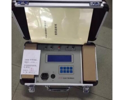
Single-Channel Partial Discharge Tester (referred to as Single-Channel PD Tester) is a professional instrument specifically used to detect partial discharge phenomena in high-voltage electrical equipment. This type of tester is typically used in laboratories or on-site testing to monitor and evaluate the insulation condition of electrical equipment. Below is an article summary about the Single-Channel PD Tester.
Single-Channel PD Tester
Partial Discharge (PD) is a discharge phenomenon that occurs in local areas of insulating materials in high-voltage electrical equipment when the electric field strength reaches a certain level. This phenomenon may be an early indicator of insulation material defects, so effective monitoring of it is crucial for predicting and preventing electrical equipment failures. The Single-Channel PD Tester is a tool specifically designed to detect and quantify partial discharge, suitable for maintenance and testing of various electrical equipment.
Working Principle
The working principle of the Single-Channel PD Tester is mainly based on the physical phenomena and changes in electrical signals that occur during partial discharge. The most common detection method is the pulse current method, which uses special sensors to capture the pulse current signals generated by partial discharge. These signals are then amplified, filtered, and analyzed by corresponding electronic devices.
Main Features
Strong anti-interference capability: Utilizes digital filtering technology to effectively eliminate on-site interference, enabling partial discharge measurement in strong interference environments.
High sensitivity: Can detect weak partial discharge signals.
High accuracy: Provides accurate and reliable data, helping to accurately assess insulation conditions.
Easy operation: Features an intuitive user interface and simple operating procedures.
Detection Methods
Startup preparation: Adjust the time base mode to “Ellipse”.
Calibration: Correctly connect the calibration pulse generator and enable calibration.
After calibration: Disconnect the calibration connection line and remove the calibration pulse generator.
Connect power: Connect to the high-voltage test circuit power supply, turn on the zero mark switch, and slowly increase the test voltage.
Observation: Two zero mark pulses appear on the display ellipse, with a phase difference of 180 degrees. Rotate the “Ellipse Rotation” to a position convenient for observing the discharge.
Partial discharge inception voltage: Continuously increase the voltage, noting the sustained discharge that appears. When the discharge amount exceeds the specified low value, the voltage at that time is the partial discharge inception voltage.
Discharge amount measurement: At the set voltage, when a discharge pulse signal is observed, adjust the amplifier switch so that the discharge pulse height is between 0.2 and 2 cm. The discharge amount is then the reading on the digital meter multiplied or divided by 10.
Application Fields
Power systems: Used for partial discharge detection in substations, transmission lines, cables, and other equipment.
Manufacturing industry: Used for quality control during production, such as factory inspection of transformers, motors, and other products.
Research institutions: Used to study the insulation performance and aging characteristics of high-voltage electrical equipment.
Technical Specifications
Detection channels: Single-channel design, suitable for detection of a single signal source.
Basic error of apparent charge q measurement: Includes linearity error, asymmetry error of positive and negative pulse response, range switching error test, low repetition rate pulse response error, and other items.
Maintenance and Care
Regular calibration: Calibrate the instrument according to the manufacturer's recommended intervals to ensure accuracy of detection results.
Cleaning and maintenance: Regularly clean the instrument surface, especially the sensor parts, to avoid dust affecting detection accuracy.
Storage conditions: Store in a dry, ventilated place, avoiding high temperature and humid environments.
Conclusion
The Single-Channel PD Tester, as a professional detection tool, plays an important role in power system maintenance and fault prevention. By accurately detecting partial discharge phenomena, it helps engineers identify potential problems in a timely manner, take measures to prevent equipment failures, and thus ensure the stable operation of the power system.
References
Yangzhou Darui Electric: Product introduction of Single-Channel PD Tester.
China Chemical Instrument Network: Detection methods and principles of Single-Channel PD Tester.
Sohu.com: Explanation of PD tester principles by Engineer Lu from Zhongshi Holding Technology Research Institute.
Renren Library: Document on technical specifications of PD testers.