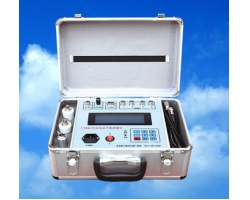
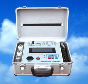
The Centrifuge Field Dynamic Balancing Measuring Instrument is a high-precision, high-performance field dynamic balancing instrument.The key technology lies in the use of advanced software and hardware digital processing technology to achieve constant bandwidth correlation filtering. It can distinguish vibration signals with a frequency difference of more than 0.2Hz, that is, at speeds greater than 12 rpm. This demonstrates the instrument's excellent filtering characteristics and strong anti-interference capability.
Under the same environmental conditions, compared to the VT700, the dynamic balancing instrument VT800 shows more stable and reliable measurements of vibration and phase angle during dynamic balancing measurement, with better repeatability and consistency, further improving the measurement accuracy of the dynamic balancing instrument, especially enhancing the field dynamic balancing application effect under small signal conditions.
Technical Parameters
1. General Measurement:
Speed Measurement: 30~30,000 rpm
Vibration Measurement: 0.01~5000μm (Peak-to-Peak)
0.01~2000mm/s (RMS)
Vibration Analysis: FFT Spectrum Analysis
Display: 64X240 Dot Matrix Graphic LCD with Chinese Menu
Three Important Requirements in Dynamic Balancing Measurement
.1, Installation of Speed Sensor
1.1, When using a photoelectric speed sensor, first make a photoelectric mark on the shaft as the zero phase. The photoelectric mark is usually made with white double-sided adhesive paper as reflective paper. The greater the contrast between the reflective paper and the color of the object being measured, the better the measurement result. If the contrast is not obvious, it is recommended to increase contrast by painting black paint or sticking black electrical tape. The width of the reflective paper should depend on the shaft diameter; for large diameter shafts, it should be wider, corresponding to an angle of about 3-5 degrees.
Use a flexible hose magnetic stand to align the red light of the photoelectric sensor's emitter tube directly at the reflective paper, with a gap of 1~30cm. Observe the red LED (operation indicator) behind the photoelectric sensor; when it receives the reflected signal, it should flash continuously. Adjust the white sensitivity knob on the photoelectric sensor so that the operation indicator flashes continuously.
Adjustment steps: First, turn the sensitivity knob counterclockwise to make the operation indicator turn green, then turn the sensitivity knob clockwise to make the operation indicator turn red and flash. Only then will the instrument display a corresponding stable speed.
1.2, When using a Hall sensor, first place a small magnet on the pulley or rotor plane as the zero phase mark. Use a flexible hose magnetic stand to fix the Hall sensor, facing the magnet, with a gap of about 5-10mm. After powering on, the indicator light on the Hall sensor lights up. At low speed rotation, the Hall sensor indicator light flashes continuously, and the photoelectric indicator on the panel also flashes continuously. The instrument will display a corresponding stable speed.
Precautions for placing the small magnet: 1. The magnet has two sides, front and back. The side with the circle mark should face outward, toward the Hall sensor, otherwise there will be no output. 2. To increase the magnet's suction and prevent it from flying off due to centrifugal force during high-speed rotation, apply a drop of 502 glue around the magnet's perimeter. 3. It is best to place the magnet on a flat surface; if there are holes, grooves, or flanges on the surface, it is safer and more reliable.
2, Installation of Vibration Sensor
2.1, Vibration sensors are divided into two types: acceleration sensors and velocity sensors. Acceleration sensors are suitable for high-frequency vibration, while velocity sensors are suitable for low-frequency vibration. Velocity sensors are passive and have better anti-interference performance than acceleration sensors. Acceleration sensors have better frequency response and linearity, which are superior to velocity sensors.
The vibration sensor is used to pick up equipment vibration signals. When in use, firmly attach the magnetic base to the measurement point, which refers to the bearing housing supporting the rotor, and the closer to the bearing housing, the better. The sensor can measure at any angle, in principle, measure in the direction where the vibration amplitude is the largest and the value is the most stable. Note that the vibration sensor should generally be installed perpendicular to the rotor axis in the horizontal direction for measurement.
2..2, The magnetic base is a mounting suction cup composed of NdFeB magnet and specially designed magnetic circuit. The M5 screw can be screwed into the lower threaded hole of the vibration sensor. This magnetic base can easily install the sensor on the bearing housing of ferromagnetic material equipment. For non-ferromagnetic material equipment, the user needs to drill and tap holes for fixation.
3, Determination of Phase Angle
Definition of zero phase angle: Viewed from the reference mark against the direction of rotor rotation, the edge from bright to dark.
The photoelectric sensor uses the position where the white reflective paper is attached as the zero degree of the phase angle. The Hall sensor uses the position where the small magnet is placed as the zero degree of the phase angle. The laser sensor uses the position where the special reflective paper is attached as the zero degree of the phase angle. Count the phase angle degrees in the direction opposite to the rotor rotation direction. This must not be mistaken, otherwise the dynamic balancing calculation result will get worse and worse.
Stable speed measurement, stable vibration signal measurement, and correct phase angle definition are the keys to the success of dynamic balancing calculation results.
During the dynamic balancing measurement process, the installation positions of the vibration sensor and speed sensor should always remain unchanged.