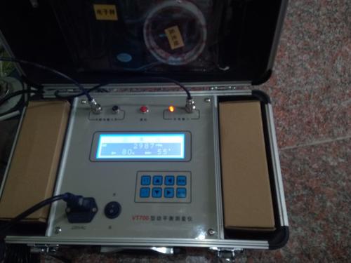
Rotating Machinery Dynamic Balancing Measuring Instrument
The mechanical rotating dynamic balancing tester can measure the rotation of on-site bearings
This instrument is simple to operate, with human-machine dialogue, menu prompts, and measurement data can be locked and held at any time. The VT balancing instrument is compact and lightweight, with the keyboard and display on the panel, while input/output sockets and various control switches are all placed on the panel. The VT balancing instrument can perform on-site dynamic balancing of various rotating machinery as a whole, equivalent to a movable balancing machine. It is exquisitely designed and portable, with the entire instrument packed in a portable instrument case.
1.Rotating Machinery Dynamic Balancing Measuring Instrument General measurement:
Speed measurement: 30~30,000 rpm
Vibration measurement: 0.01~5000μm (peak-to-peak)
0.01~2000mm/s (RMS)
Vibration analysis: FFT spectrum analysis
Display mode: dot matrix graphics 64X240 dot matrix graphic LCD Chinese menu
Keyboard: eight keys
2. Dynamic balancing measurement:
Number of measurement points: single point or single plane double points or double planes
Vibration signal frequency band: 5Hz~1KHz
Same-frequency operating speed: 300~30,000 rpm
Same-frequency amplitude range: 0.01~5000μm (peak-to-peak)
Vibration severity range: 0.01~2000mm/s (RMS)
Phase accuracy: 0-360°±1 °
Unbalance reduction rate: ≥85%
Note:
1) When using ultra-low frequency magnetoelectric sensors or eddy current sensors to measure vibration signals, the same-frequency operating speed can be reduced to 30 rpm.
2) When the equipment operating speed exceeds 10,000 rpm, please purchase a laser speed sensor separately.
Three requirements in dynamic balancing measurement of PHY balancing tester
3.1. Installation of speed sensor
3.1.1. The Hall speed sensor should be connected to the photoelectric input socket on the instrument panel (pay attention to the concave and convex positions of the four-core socket plug). When using the Hall sensor, the mechanical rotating dynamic balancing tester should first place a small magnet on the pulley or rotor plane as a zero-phase mark. Use a hose magnetic base to fix the Hall sensor, facing the magnet, with a gap of about 5-10mm. After powering on, the indicator light on the Hall sensor lights up, and when leaving, the indicator light goes off. During low-frequency rotation, the Hall sensor indicator light flashes continuously, and the photoelectric indicator light on the panel also flashes continuously. The instrument should display a corresponding stable speed.
Precautions for placing small magnets: 1. The magnet has two sides, front and back. The side with the circle mark faces outward, facing the Hall sensor, otherwise there will be no output. 2. To increase the magnetic attraction and prevent the magnet from flying out due to centrifugal force during high-speed rotor operation, use 502 glue to drip a circle around the magnet. 3. If there are holes, grooves, or flanges on the plane where the magnet is placed, it is safer and more reliable to place it there.
2. When using the photoelectric speed sensor, the mechanical rotating dynamic balancing tester should first make a photoelectric mark on the shaft. The photoelectric mark is usually a black/white mark. Clean the shaft surface, then paint it all black with black paint or black tape, and then cut a piece of tin foil or reflective adhesive paper and stick it on. The width of the reflective paper should depend on the shaft diameter; for large-diameter shafts, the mark should be wider. The photoelectric mark requires clear black and white contrast and neat edges. Using special reflective paper is more effective.
Use a hose magnetic base to face the photoelectric sensor to the photoelectric mark, with a gap of 5~30mm. Pay attention to the orange light-emitting tube (action indicator light) on the photoelectric sensor. When the action indicator light normally receives the reflected signal, it should flash continuously. Adjust the sensitivity knob on the photoelectric sensor so that the action indicator light flashes continuously (pay attention to safety at this time), and the instrument will display a corresponding stable speed. Otherwise, adjust the distance of the photoelectric sensor or redo the photoelectric mark.
3.2. Installation of vibration sensor
3.2.1 The vibration sensor is used to pick up equipment vibration signals. When in use, it should be firmly attached to the measuring point with a magnetic base, pointing to the bearing housing supporting the rotor, and the closer to the bearing housing, the better. The sensor can measure at any angle; the principle is to measure in the direction where the vibration amplitude is maximum and the value is most stable. Generally, it is installed horizontally for measurement.
3.2.2 The magnetic base is a specially designed mounting suction cup composed of high-strength aluminum-iron-boron magnets and a specially designed magnetic circuit. The top M5 screw can be screwed into the lower threaded hole of the vibration sensor. This magnetic base can easily install the sensor on the bearing housing of ferromagnetic material equipment. For non-ferromagnetic material equipment, users need to drill holes and tap threads for fixing, and the screw depth should be less than 5mm. The magnetic base has strong suction and can easily pinch fingers, so operation should be very careful for safety.