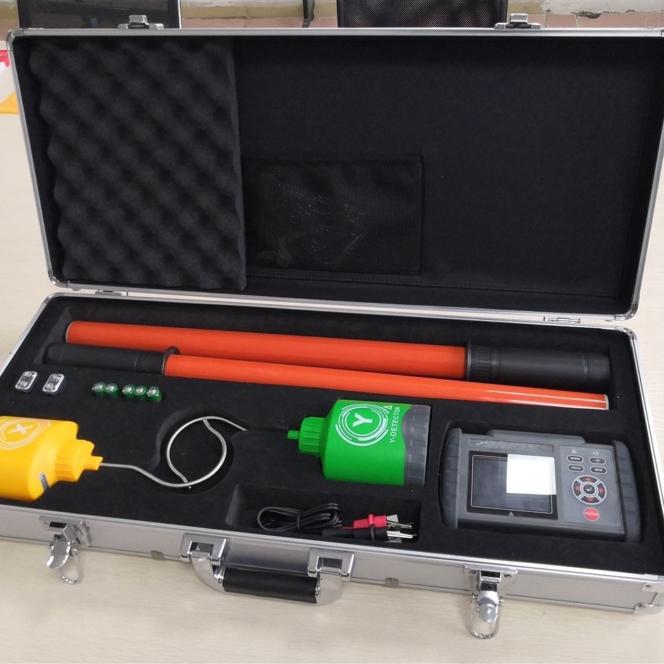
Digital High Voltage Wireless Phase Detector
Digital High Voltage Wireless Phase Detector Usage Method and Technical Parameters:
1. Accuracy: Same phase error ≤15°, different phase error ≤15°
2. Sampling rate: 3 times/second
3. X and Y collector power supply voltage: 7.5V ±1.5V
4. X and Y collector working current ≤5mA
5. Visual transmission distance between host and X, Y collectors: X, Y ≥20m
6. Working environment: 0° to 50°, humidity: ≤85%RH
7. Storage environment: 0° to 55°, humidity: ≤85%RH
8. Voltage levels measured by this product: 0.38KV to 220KV
Digital High Voltage Wireless Phase Detector Usage Method and Product Features:
1. Screen display content: Wireless high voltage phase detector, different phase, same phase, frequency, X, Y
2. Power: The host uses a rechargeable power source, and the X and Y collectors use 5 AG10 batteries.
3. Auto power off: The host will automatically power off about 8 minutes after startup.
4. When in contact with the measured strong electric field, the instrument will automatically alarm.
On-site phase verification instructions:
① First, hang the X and Y collectors on the same high-voltage line respectively. The host display should show X and Y in the same phase, with a phase difference of 000° to 001°.
② When verifying phase on high-voltage lines, arrange the X and Y collectors as follows for phase verification: AA′ same phase 000° to 001°: AB′ different phase 120° or 240°, BB′ same phase 000° to 001°, BC′ different phase 120° or 240°, CC′ same phase 000° to 001°.
③ To obtain the optimal value, place one collector at a fixed point on the high-voltage line, and move the other collector around another point on the high-voltage line front, back, left, and right, or swap X and Y to find the best phase angle.
④ During phase verification, if the test data for AA′, AB′, BB′, BC′, CC′ all show different phases, this is because the two sets of power supply lines being tested have different wiring groups, which may result in a phase difference of 30° or 60°. The following describes the measurement standard in this case (using a 30° phase difference as an example): The test method is the same as ① and ②, and the results should be: AA′ different phase 30°, AB′ different phase 120° or 240°, BB′ different phase 30°, BC′ different phase 120° or 240°, CC′ different phase 30° (Note: 120° and 240° only indicate positive or negative phase sequence).
⑤ When measuring ≥10KV, X and Y can be directly placed on the conductor or insulation layer for phase verification.
⑥ When verifying phase at ≥66KV, the X and Y collectors can use contact or non-contact methods. (For example, when measuring 110KV and 220KV, place the X and Y collectors 300mm to 1000mm below the high-voltage wire. When measuring 500KV, place the X and Y collectors 1000mm to 2000mm below the high-voltage wire, with an allowable deviation of 300mm left and right.)
⑦ Measuring phase sequence: Assume a certain line is phase A. Place X on phase A and Y on another phase. If it displays 120°, it indicates a positive phase sequence, and that phase should be "B". If it displays 240°, it indicates a negative phase sequence, and that phase should be "C".
⑧ Voltage detection: Hang one collector on a high-voltage wire. If the host screen displays the corresponding collector symbol, it indicates that the high-voltage wire is live. Conversely, if the host screen does not display the collector symbol, it indicates that the high-voltage wire is not live (but the collector cannot replace a voltage detector).