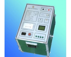
Variable Frequency Anti-Interference Dielectric Loss Tester
Product Introduction:
Variable Frequency Anti-Interference Dielectric Loss Testeris an advanced instrument for measuring dielectric loss tgδ and capacitance Cx, used for measuring dielectric loss tgδ and capacitance Cx of various insulating materials, insulating bushings, power cables, capacitors, transformers, and other high-voltage equipment under power frequency high voltage. It replaces the QSI high-voltage bridge, featuring simple operation, Chinese display, printing, convenient use, no conversion needed, built-in high voltage, strong anti-interference capability, and short test time. It is our factory's third-generation intelligent dielectric loss tester.
Principle Description:
The instrument's measurement circuit includes a standard circuit and a test circuit, as shown in Figure 3.
The standard circuit consists of a built-in high-voltage stable standard capacitor and a standard resistor network. The computer collects the current amplitude and phase difference of the standard circuit current and the test circuit current in real time, and calculates the capacitance value CX and dielectric loss tgδ of the tested object.
The data acquisition circuit uses high-voltage stable components entirely. The acquisition board and acquisition computer are completely floating and shielded by an iron box, and the instrument shell is grounded and shielded. In addition, anti-interference technologies such as optical data transmission, floating ground, large-area ground, single-point ground, and digital filtering are used. Combined with the computer processing data from hundreds of power grid cycles, the measurement results are stable and reliable.
The high-voltage side of the instrument's high-voltage transformer and the measurement circuit are floating. Users can flexibly adopt various grounding methods according to different measurement objects and needs. For example, when using the "positive connection method" for measurement, point "E" can be grounded; when using the "reverse connection method" for measurement, point "UH" can be grounded, and point E can be left floating.
In the figure, except for the test object CX, the rest is this instrument. The part inside the thin line frame is subjected to 15KV power frequency high voltage for 5 minutes with the instrument shell, and the rated withstand voltage is 10KV. The instrument has a built-in standard capacitor CN with a nominal value of 50PF, tgδ≤0.0001, and a withstand voltage of 10KV. The high-voltage transformer has a rated output power of 1.5KVA.
Point "E" is connected to the internal shield of the instrument and the shield layer of the measurement cable. It is not the earth and is not connected to the instrument shell!!!
Structure Description:
The instrument has an integrated structure of voltage boosting and measurement. The output voltage is adjustable in five gears from 2.5KV to 10KV to meet various needs. No external equipment is required during measurement. The wiring is similar to the QSI bridge but more convenient.
1. Display window - LCD screen.
2. Test voltage selection switch - When the switch is set to "Off", the instrument has no high-voltage output.
3. Operation keyboard - Used to select measurement mode, start, stop, print, and other operations.
4. Power socket - Fuse is 5A.
5. Power switch - Power on/off.
6. Start lamp - Indicates high-voltage output.