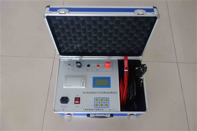
Loop Resistance Tester
Performance Features:
The MS2520H-I model loop resistance tester is precision-crafted using advanced high-power switching power supply technology and sophisticated electronic circuits. It is a dedicated testing instrument for contact resistance of high and low voltage switches, cables, wires, and weld seams. Its current adopts the 100A DC recommended by the national standard GB736, and can measure the resistance value of the test object at 100A current. This instrument features dual LCD screens for displaying resistance and current values, overcoming the disadvantage of red digital tube displays being difficult to read in sunlight. It has the characteristics of small size, light weight, strong anti-interference capability, high accuracy, easy operation, and comprehensive protection functions.
Technical Parameters
1. Measurement range: 0~4mΩ (50A gear) 0~2mΩ (100A gear) 0~1.33mΩ (150A gear) 0~1mΩ (200A gear)
2. Test current: DC50A, 100A, 150A, 200A fixed output
3. Measurement accuracy: ±(0.5% rd+2d)
4. Continuous working time: 5s~599s
5. Display mode: large-screen Chinese LCD display
6. Communication method: RS232 serial port
7. Working power supply: AC220V±10% 50Hz
8. Total power: 1200W
2. Turn on the power.
3. Press the measurement button (if the current display A value is less than 100A, it can be corrected via the panel current fine-tuning).
4. After the measurement value is displayed, save the data if needed.
5. After the measurement, please turn off the power.
6. Please take care of the test clamps.
Instructions for Use
1. According to the four-wire measurement method, use the dedicated test leads to connect the test object to the instrument panel. Note that the voltage measurement leads should be connected inside the current output leads.
2. Connect the AC220V power supply (note: the third wire of the power input, i.e., the protective ground, must be connected to the earth), press the power switch, and the current meter and resistance meter will display "000" (a one-digit fluctuation is allowed).
3. Press the measurement switch, adjust the current output knob (clockwise) until the current meter head displays "100.0", then read the number on the resistance meter head as the resistance value of the test object, and record it. (If "1" is displayed, it indicates that the measured circuit is over-range).
4. After testing, turn the current output adjustment knob (counterclockwise) to the minimum, reset the measurement switch, and then turn off the power switch.
5. To repeat the test, simply reset the measurement switch, re-clamp the test clamps, and press the measurement switch again.