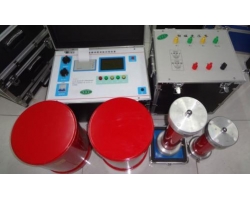
In power systems, ensuring phase consistency between different power sources or equipment is crucial for preventing electrical accidents and ensuring stable operation. Traditional phase verification methods often require operators to directly contact high-voltage conductors, posing certain safety risks. As an advanced technical tool, the high-voltage wireless phase verifier can accurately compare phases without contacting high-voltage conductors, greatly enhancing the safety and convenience of phase verification work.
Working Principle of High-Voltage Wireless Phase Verifier
The high-voltage wireless phase verifier typically consists of a transmitting unit, a receiving unit, and a control unit. The transmitting unit is placed near the high-voltage conductor to be tested, obtains voltage signals through induction, and transmits these signals wirelessly to the receiving unit. After receiving the signals, the receiving unit processes them and compares them with a reference signal to ultimately determine whether the phases are consistent. The entire process does not require physical connection to the high-voltage conductor, thereby improving operational safety.
Main Functional Features
Wireless Transmission: Utilizes wireless technology to complete phase comparison without physical connection, reducing the risk of operators contacting high-voltage conductors.
High Safety: Operators do not need to directly contact high-voltage conductors, reducing the risk of electric shock.
Long-Distance Operation: Supports signal transmission over longer distances, convenient for use in complex environments.
Multifunctional Display: Equipped with a clear display screen showing phase difference, frequency, and other information for easy reading by operators.
Data Recording and Analysis: Some advanced models support data recording and analysis functions, facilitating subsequent processing and archiving.
Phase Verification Steps
Preparation: Ensure operators wear personal protective equipment (such as insulating gloves, insulating shoes, etc.) and confirm the instrument is in good condition.
Transmitter Positioning: Place the transmitting unit near the high-voltage conductor to be tested, ensuring it can sense the voltage signal.
Receiver Setup: Place the receiving unit in a safe location, turn on the instrument, and the receiving unit begins to receive signals from the transmitting unit.
Signal Processing and Comparison: The receiving unit processes the received signals and compares them with the reference signal to determine whether the phases are consistent.
Result Reading: Read the phase difference information on the display screen of the receiving unit to determine consistency.
Recording and Analysis: Record the test results and conduct further analysis as needed.
Application Scenarios
Power System Maintenance: Used to detect phase matching of lines or equipment during maintenance to ensure correct phase sequence connections.
New Project Acceptance: Used in acceptance tests for new power facility projects to ensure correct phase connections and avoid equipment damage due to phase errors.
Fault Diagnosis: Helps locate problems when abnormalities occur in the power system, especially when phase inconsistency is suspected.
Research and Teaching: Used as an experimental tool in power engineering research and teaching activities to help students understand and master phase comparison methods and techniques.
Operational Precautions
Safety First: Always follow safety operating procedures, especially when working in high-voltage environments, ensuring personal protective equipment is complete.
Environmental Factors: Pay attention to temperature, humidity, and other conditions of the test environment to avoid interference with signal transmission.
Instrument Calibration: Regularly calibrate the instrument to ensure the accuracy of test results.
Professional Training: Operators should receive professional training to become familiar with the instrument's usage methods and safety knowledge.
Typical Case
Case Description: For example, during a certain power system maintenance task, technicians used a high-voltage wireless phase verifier to compare the phases of two high-voltage lines. Through the wireless phase verifier, technicians were able to quickly and accurately determine whether the phases of the two lines were consistent and promptly took measures to adjust.
Problem Discovery: A phase difference between the two lines was discovered, which could lead to equipment damage or system failure if not adjusted in time.
Solution: By adjusting the connection method, the phases of the two lines were ensured to be consistent, avoiding potential safety hazards.
Conclusion
The high-voltage wireless phase verifier, with its high safety, convenience, and accuracy, has become an ideal tool for phase comparison in power systems. By using this advanced instrument, power engineers can perform phase verification more effectively, ensuring the safe and stable operation of the power system.
Outlook
With the continuous development of wireless communication technology and sensor technology, future high-voltage wireless phase verifiers will become more intelligent, with stronger data processing capabilities and remote monitoring functions, further improving the operation and maintenance efficiency and safety of power equipment.
This article outline provides readers with basic knowledge and application guidance about the high-voltage wireless phase verifier. When writing a detailed article, more technical details and actual case analyses can be added based on specific circumstances.