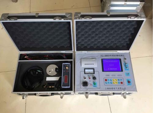
Cable Fault Detector
I. Main Technical Indicators of Cable Fault Detector:
1. Detection methods: low-voltage pulse method, high-voltage flashover method.
2. Technical parameters
① Test distance: for low-voltage pulse method, max test distance 16Km; for high-voltage flashover method, max test distance 15Km.
② System test accuracy: less than 20cm.
③ Pulse amplitude: not less than 250Vpp when load impedance is 50Ω.
④ Length selection: ﹤1KM, ﹤3KM, >3KM three types.
⑤ Sampling frequency: 6MHz, 12 MHz, 24MHz, 48 MHz.
⑥ Reading resolution: 1m
⑦ Preset wave propagation speeds for 4 cable media: oil-impregnated paper, non-drip: 160m/μs; cross-linked polyethylene: 172m/μs; polyvinyl chloride: 184m/μs; rubber sheathed cable: 100m/μs; and self-setting for other types of cables.
⑧ For other types of cables, using the speed measurement function of this device, after inputting the known total length of the cable type, the propagation speed of the wave in that cable can be measured.
3. Sampling methods: current sampling method, voltage sampling method.
4. Working conditions: temperature -20 ~ +55°C, relative humidity 90%.
5. Dimensions: 430×300×190mm.
6. Weight: about 10kg.
Shanghai Laiyang Electric Co., Ltd. "Honest service, making friends widely" is the company's firm business philosophy. We strictly and conscientiously fulfill contracts, honor commitments, strengthen the after-sales service network, guide our service with newer and higher ideas, and dedicate newer and higher products to you. Let our efforts become your satisfaction. All employees of our company look forward to your visit and guidance.
Laiyang Electric always adheres to the tenet of"Carefully craft high-quality products, repay customers with quality", and strictly implements the "After-sales Service Commitment". We firmly believe that high-quality, systematic, comprehensive, and fast service is the foundation for business development. Establish a sound mechanism, incorporate work into enterprise management, and persist in continuous efforts.
II. Composition Block Diagram of Cable Fault Testing Device
The system block diagram is shown in Figure 1.
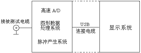
Figure 1 System Block Diagram
When selecting "low-voltage pulse method", a 250VPP test pulse signal is applied to the cable under test and the input circuit of the host. The test waveform is displayed on the screen after signal and data processing.
At the same time, the status display bar shows cable type, wave propagation speed, sampling frequency, fault distance, test date, etc.
When selecting "high-voltage flashover method", the internal pulse signal is disconnected, and the instrument is in an external trigger waiting state. When the impact high voltage applied to the cable under test causes the fault point to flashover discharge, the single flashover waveform is input to the instrument through the current sampler, the instrument starts sampling, and displays the test waveform.
III. Test Principle
Cable faults are generally divided into two categories: short circuit, open circuit, low resistance faults and high resistance flashover, leakage faults. According to the radar ranging principle, a pulse signal is emitted from the test end to the cable. At the place where the characteristic impedance is mismatched, a reflected wave is generated. The incident waveform and reflected waveform are collected and displayed on the screen, and the double electronic cursors are placed on the two characteristic inflection points of the waveform. Based on the propagation speed of the wave in this type of cable, the distance from the fault point to the test end can be calculated.
S = VT / 2
S: distance from the fault point to the test end.
V: propagation speed of the wave in the cable.
T: time required for the wave to travel back and forth between the test end and the fault point.
When V and T are known, S can be calculated. Simply place the double electronic cursors on the characteristic inflection points of the waveform, and it can be completed automatically.